How to use the TF Mini-S LiDAR Sensor with Arduino UNO (Using Linux-Ubuntu)
In this project-tutorial, we will be learning how to interface the TF Mini-S LiDAR time-of-flight (ToF) distance sensor module with the Arduino UNO R3 using Linux-Ubuntu…
Background
The TFMini-S is a miniaturized single-point ranging LiDAR (Light Detection & Ranging) sensor module that is an upgrade based on the TFMini from Benewake, a Chinese company that specializes in developing technologies for autonomous driving. It is based on the time-of-flight (ToF) principle and it is designed with unique optics & algorithms to achieve stability, precision, sensitivity and high speed distance measurement functionalities. It is compatible with both UART and I2C communication interfaces which can be switched by use of commands.
Main Features of the TFMini-S
- Small size
- Light weight
- Lower power consumption
- High frame rate (up to 1000Hz)
- Higher distance measurement accuracy
- Compatible with both UART & I2C
- Flexible detection frequency
- Detection blind zone of 0-10cm
Main Applications
- Vehicle detection
- Pedestrian detection
- Intelligent barrier gate
- Altimeter
How the TFMini-S LiDAR works (ToF Principle)
The TFMini-S operates basing on the Time-of-Flight (ToF) principle and to be specific, the sensor emits modulation waves of near infrared rays in a periodic basis which are reflected after contacting an object. The sensor module obtains the time of flight by measuring the round-trip phase difference and then calculates the range between the sensor and the detected object as shown in the figure below;
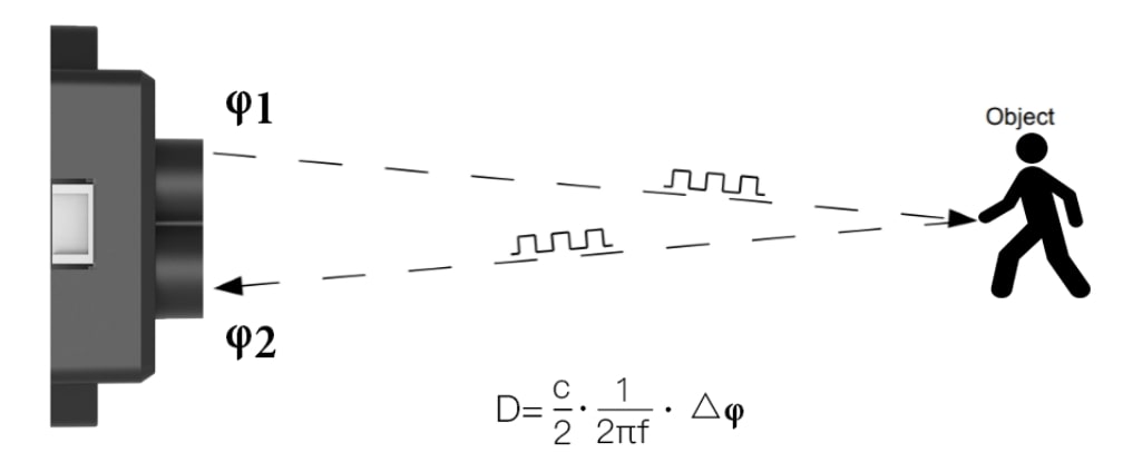
Image Source
https://en.benewake.com/
Here is a general overview of the operation of the TFMini-S Lidar Sensor
Emitting a Light Signal: The TF Mini-S lidar sensor emits an infrared (IR) light signal in the form of a pulsed beam. This IR light is invisible to the human eye.
Emitting Pattern and Beam Width: The sensor emits the IR light in a specific pattern, usually a conical shape, with a certain beam width. The emitted beam spreads out as it travels away from the sensor.
Reflection from Objects: When the IR light beam encounters an object within its range, a portion of the light is reflected back towards the sensor.
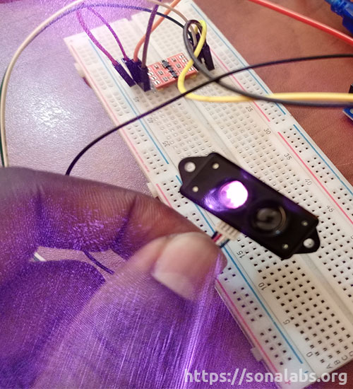
Receiving the Reflected Light: The sensor has a receiver that detects the reflected light signal. It measures the time it takes for the light to travel to the object and return to the sensor.
Time-of-Flight Calculation: Using the measured time and the speed of light, the sensor calculates the distance between itself and the object. The speed of light is a known constant, so by measuring the time it takes for the light to travel, the distance can be determined.
Distance Measurement Output: The TF Mini-S sensor provides the calculated distance as an output, usually in centimeters (cm) or meters (m). This information can be read and utilized by a microcontroller such as an Arduino UNO or a computer for further processing or decision-making.
It’s important to note that the TF Mini-S lidar sensor operates based on the principle of direct reflection. It measures the distance to objects that reflect the emitted light back to the sensor. Transparent or highly reflective surfaces may not reflect the IR light effectively and may result in inaccurate distance measurements.
TFMini-S Pinout
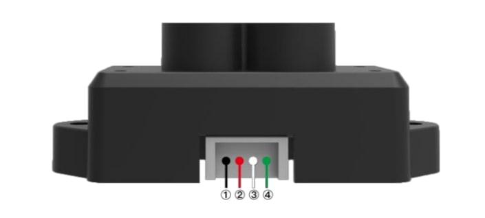
Image Source
https://en.benewake.com/
The TF-Mini-S LiDAR Sensor module has four wires; black, red, white and green as shown in the figure above and their functions are shown in the table below;
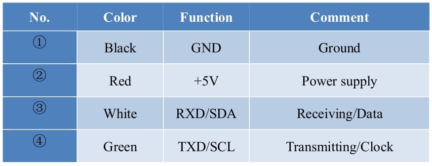
Image Source
https://en.benewake.com/
TFMini-S Appearance & Structure
Below is the cross-section of the TFMini-S module with units in mm.
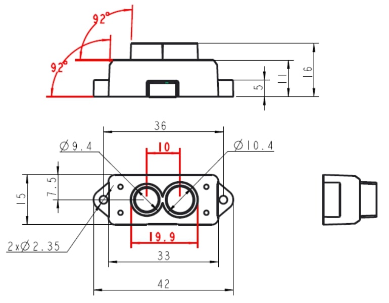
Image Source
https://en.benewake.com/
Main Characteristics Parameters
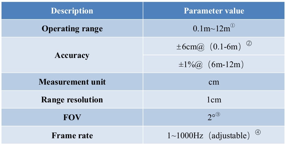
Image Source
https://en.benewake.com/
Electrical Characteristics
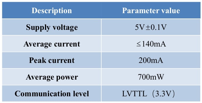
Image Source
https://en.benewake.com/
Serial port communication protocols (UART & I2C)
The TFMini-S LiDAR module can be used via two communication protocols, i.e via UART or I2C. The specifications for these interfaces are shown in the tables below;
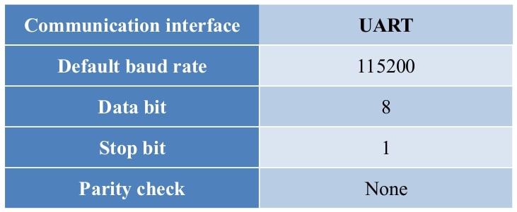
Image Source
https://en.benewake.com/
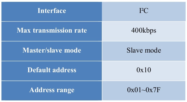
Image Source
https://en.benewake.com/
Contrary to UART, the I2C communication is initiated by the master device while the TFMini-S is used as a Slave device to only send and receive data passively.
Data output of serial port
The TFMini-S is available with two formats of data output namely; the standard data output format and the character string data format, both of which are switchable with commands. For the purpose of this project-tutorial, we shall stick to the default standard data output format.
In the standard data output format, each data frame within the data structure contains 9 bytes, including the distance value, signal strength, temperature of chip and data check byte (Checksum). The data format is hexadecimal (HEX) and the data codes are as shown in the table below;
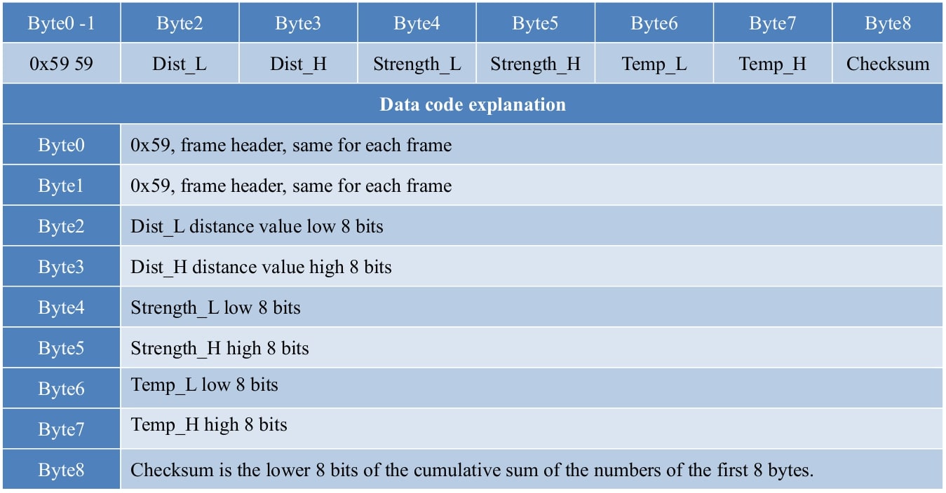
Image Source
https://en.benewake.com/
Interfacing TF Mini-S with Arduino UNO R3
Hardware Requirements
- Arduino UNO Board (1pc)
- Breadboard (1pc)
- TF Mini-S LiDAR (1pc)
- 4-Channel Logic Converter (1pc)
- USB Cable for Arduino UNO (1pc)
- Jumper wires (6pcs M-2-M)
Procedure for connection
Step-1: The Arduino-TFMini-S Circuit Build
Connect the Arduino UNO R3 to the TF Mini-S Lidar Module as shown in the circuit diagram below;
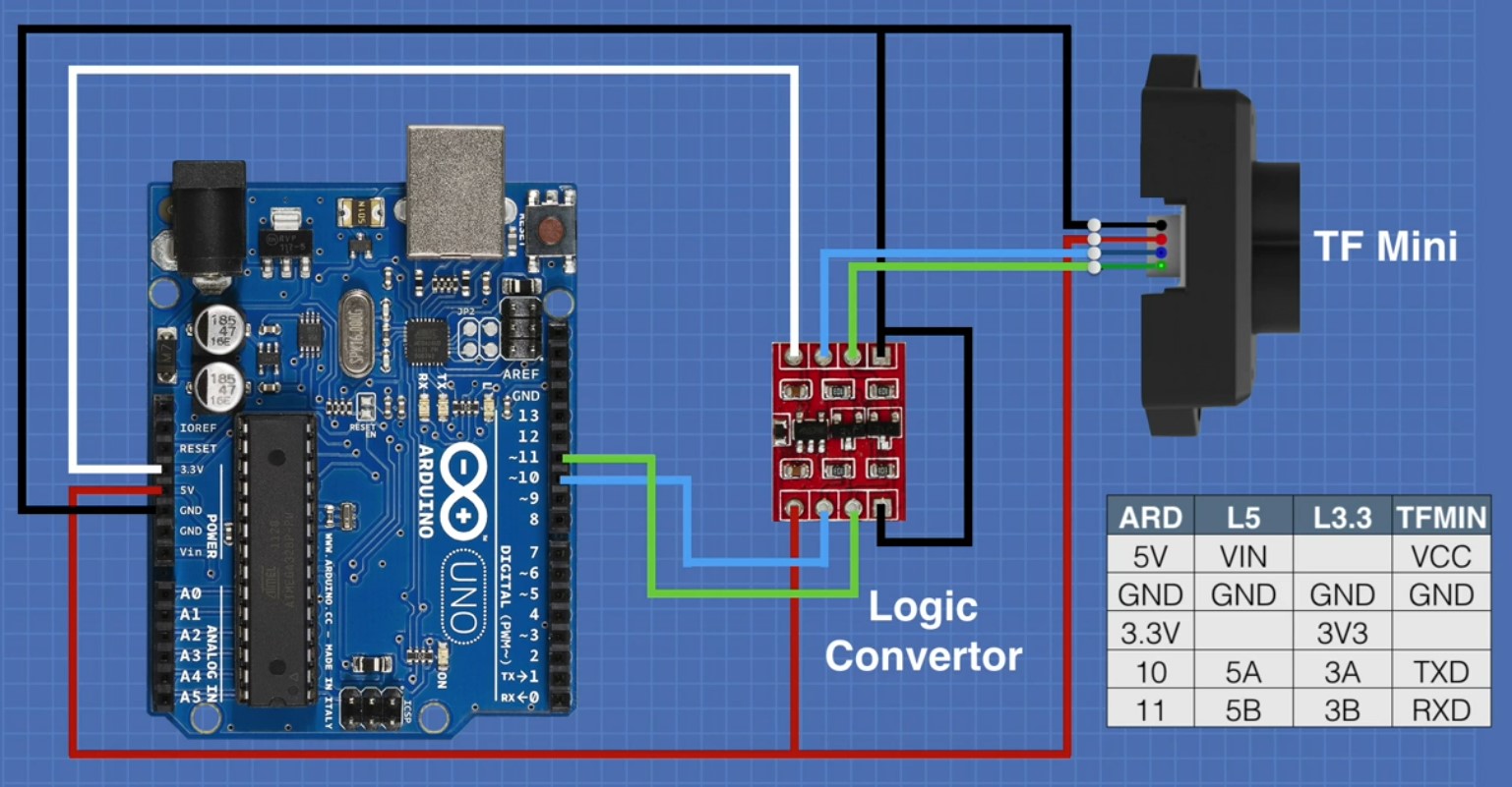
Image Source
https://dronebotworkshop.com/
The logic converter in the circuit above converts the 3.3v logic signals from the TFMini-S to the 5v logic signals required by the Arduino UNO R3 Board.
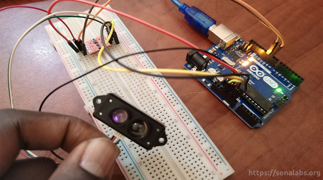
This is how our completed circuit looks like…
Step-2: TF Mini Library installation
After ensuring that all connections are perfectly snag, then open the Arduino IDE.
The first thing to do here is to open up the Arduino Library Manager by going to Sketch → Include Library → Manage Libraries as shown in the figure below;

This will open up your Library Manager and under the field of “filter your search” type in TFMini, and this will bring a list of all libraries associated with TFMini but the one we’re interested in is the one shown in the figure below;
Click on install to install the TFMini library to your Arduino IDE.

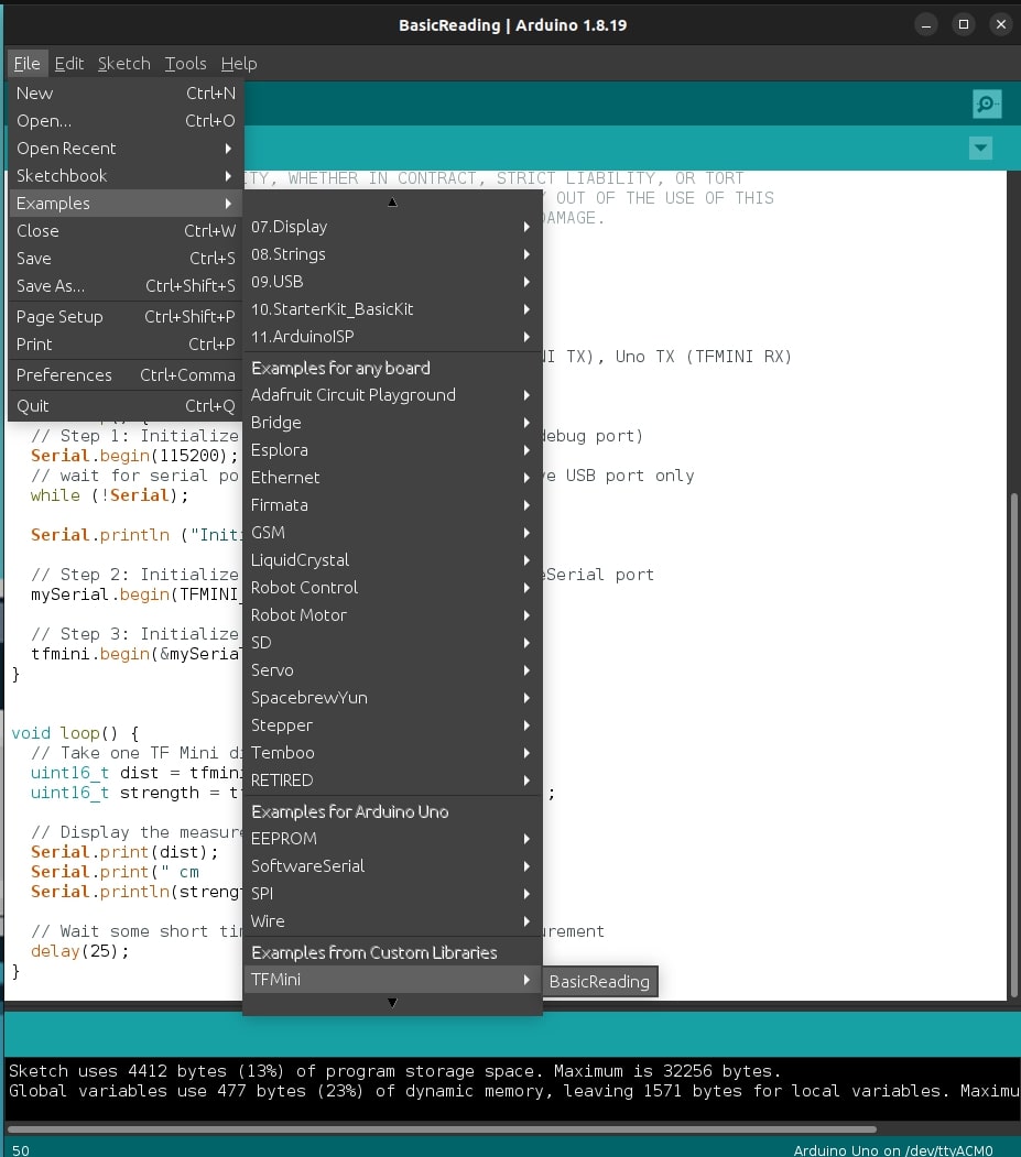
After this is done, head to the “examples” and open the “TF Mini – BasicReading” sample sketch found under “Examples from Custom Libraries” as shown below;
Step-3: Arduino IDE Error troubleshooting on Linux
For windows users, in case you encounter any error(s) while uploading the sketch to the Arduino UNO board, please refer to this tutorial for guidance.
If your using Linux like we’re here at SonaLabs, then upon verifying and uploading the BasicReading sketch to the Arduino UNO – TF Mini-S Lidar circuit, you will encounter an error as shown below;

The error message above simply indicates a permissions issue with the serial port device “/dev/ttyACM0” and to solve this problem, you can try the following steps:
1. Open terminal and run the following command:
groupsHere you will want to check if you’re a member of the “dialout” group which grants access to serial ports.
Look for “dialout” in the output and if its not listed, add yourself to the “dialout” group by running this command:
sudo usermod -aG dialout $USERAfter running the command above, you will need to close the Arduino IDE if it’s open and also log out of Linux and log back in for the changes to take effect.
Once logged in again, open the Arduino IDE and try re-uploading the BasicReading Sketch again. Ideally at this point, the sketch should be running/compiling upon uploading it to the Arduino UNO but in case the error persists, use the following commands to rectify the issue.
Open terminal and run the following commands;
ls -l /dev/ttyACM0This command verifies the permissions of the serial port device and upon running it, the output should display the permissions for the device file and it should be something like this;
crw-rw---- 1 root dialout 188, 0 Jul 11 10:00 /dev/ttyACM0If the group is not set to “dialout”, you can change it by running the following command;
sudo chown root:dialout /dev/ttyACM0so the command above sets the owner to “root” and the group to “dialout”.
Finally run the following command to ensure that the permissions of the serial port device are correctly set.
sudo chmod 660 /dev/ttyACM0This command grants read and write permissions to the owner and group, while denying access to others.
After following these steps, you should have the necessary permissions to upload your sketch using the Arduino IDE on Linux.
The BasicReading Arduino Sketch
#include <SoftwareSerial.h>
#include "TFMini.h"

// Setup software serial port
SoftwareSerial mySerial(10, 11);      // Uno RX (TFMINI TX), Uno TX (TFMINI RX)
TFMini tfmini;

void setup() {
  // Step 1: Initialize hardware serial port (serial debug port)
  Serial.begin(115200);
  // wait for serial port to connect. Needed for native USB port only
  while (!Serial);

  Serial.println ("Initializing...");

  // Step 2: Initialize the data rate for the SoftwareSerial port
  mySerial.begin(TFMINI_BAUDRATE);

  // Step 3: Initialize the TF Mini sensor
  tfmini.begin(&mySerial);
}

void loop() {
  // Take one TF Mini distance measurement
  uint16_t dist = tfmini.getDistance();
  uint16_t strength = tfmini.getRecentSignalStrength();

  // Display the measurement
  Serial.print(dist);
  Serial.print(" cm      sigstr: ");
  Serial.println(strength);

  // Wait some short time before taking the next measurement
  delay(25);
Upon uploading the BasicReading sketch above to the Arduino UNO and using the Serial Monitor for visualization, you will encounter an error message as shown in the figure below;
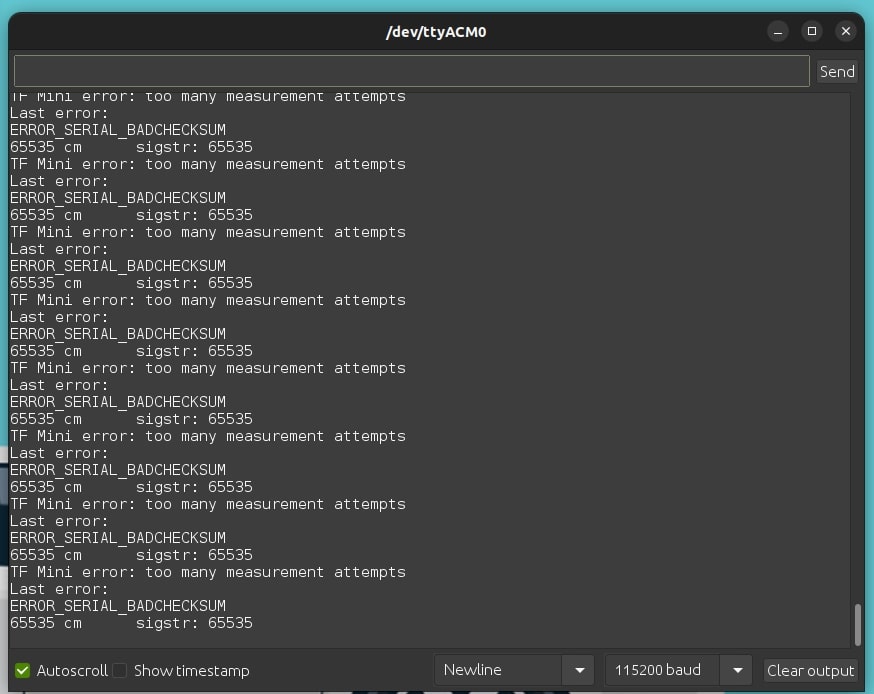
This error message suggests that there is an issue with the communication between the TF Mini-S LiDAR and your Arduino board. You can try the steps below to troubleshoot and resolve the problem;
- Double check the wiring especially on the Tx & Rx pins.
- Check the baud rate, ensure they match, the default baud rate for TF-Mini is 115200.
- Verify the power supply to both the Arduino UNO and the TF-Mini-S, ensure there is sufficient power to both.
- Test with a different Arduino Board or USB cable.
- Reset the LiDAR by disconnecting and reconnecting its power supply.
- Check for software issues by reviewing the code in the sketch to ensure it properly handles the LiDAR data.
After encountering numerous errors, we followed the above troubleshooting steps and realized the problem was with that BasicReading sketch, it just couldn’t communicate well to the TFMini-S LiDAR and so we did some digging on the internet in quest for a solution and with a little tweaking to the obtained sketch, we came up with the code below. The sketch below is well commented, you can follow along and understand it line by line.
/*
The (UNO) circuit:
 * Uno RX is digital pin 10 (connect to TX of TF Mini)
 * Uno TX is digital pin 11 (connect to RX of TF Mini)
 */

 // library needed for communicating with the TF Mini-S Lidar Sensor.
#include <SoftwareSerial.h>

// The TF Mini Header file contains the definitions of the TF Mini class
#include "TFMini.h"

// Creates a TF Mini object called tfmini
TFMini tfmini;

// Setup software serial port
// Uno Rx (TF Mini Tx), Uno Tx (TF Mini Rx)

SoftwareSerial SerialTFMini(10, 11);


// Function that gets the distance and strength data from the TF Mini sensor.
// The first parameter is a pointer to an integer that will store the distance data &
// The second parameter is a pointer to an integer that will store the strength data
// This function serves to extract data from the TFMini sensor & update the values pointed to
// by 'distance' & 'strength'.

void getTFminiData(int* distance, int* strength)
{
  // Declare & initialize several variables used within the 'getTFMiniData' function.
  // 'i' is a counter used to keep track of the index for received data.
  static char i = 0;

  // 'j' is a counter used in the checksum calculation loop
  char j = 0;

  // 'checksum' is a variable used to calculate the checksum value
  int checksum = 0;

  // 'rec' is an array of size 9 used to store the received data bytes
  static int rec[9];

  // The while loop ensures that all the available bytes are read from the SerialTFMini object.
  while (SerialTFMini.available())
  {
    // Read a byte from the 'SerialTFMini' object & store it in the 'rec' array at the current index 'i'.
    rec[i] = SerialTFMini.read();

    // This if statement checks if 'i' is 0 and the received data at index 0 is not equal to '0x59'
    // '0x59' is an hexadecimal value that represents the start of a data frame.
    if (i == 0 && rec[0] != 0x59)
    {
      // if the condition is true, it resets 'i' to 0.
      i = 0;
    }

    // This 'else if' statement checks if 'i' is 1 and the received data at index 1 is not equal to '0x59'
    else if (i == 1 && rec[1] != 0x59)
    {
      // if the condition is true, it resets 'i' to 0.
      i = 0;
    }

    // This checks if 'i' is 8 - meaning all the 9 bytes of the data frame have been received.
    else if (i == 8)
    {
      // It then calculates the checksum by summing up the first 8 bytes in the 'rec' array.
      for (j = 0; j < 8; j++)
      {
        checksum += rec[j];
      }

      // If the received checksum at 'rec[8]' matches the calculated checksum, the 'distance' & 'strength'
      // values from the received data are extracted and the pointers are updated.
      if (rec[8] == (checksum % 256))
      {
        *distance = rec[2] + rec[3] * 256;
        *strength = rec[4] + rec[5] * 256;
      }

      // Resets 'i' to 0 to prepare for the next data frame
      i = 0;
    }

    // This is executed when none of the previous conditions are met.
    // It increments 'i' to move on to the next byte in the data frame.
    else
    {
      i++;
    }
  }
}


void setup()
{
  //Initialize hardware serial port (serial debug port)
  Serial.begin(115200);

   // wait for serial port to connect. Needed for native USB port only
  while (!Serial);
  Serial.println ("Initializing...");

   //Initialize the data rate for the SoftwareSerial port
  SerialTFMini.begin(TFMINI_BAUDRATE);

  //Initialize the TF Mini sensor
  tfmini.begin(&SerialTFMini);
}

void loop()
{
  // Declare & initialize two variables (distance & strenght) to zero.
  int distance = 0;
  int strength = 0;

  // Call the 'getTFMiniData' function to retreive the latest distance & strength values from the TF Mini Sensor
  getTFminiData(&distance, &strength);

  // The while loop is executed as long as the 'distance' value is zero (false)
  // It ensures that valid distance data is obtained from the sensor.
  while (!distance)
  {
    // Within the while loop, the 'getTFMiniData' function is called again to update the ('d & s') values
    getTFminiData(&distance, &strength);

    // The 'if' statement checks if the 'distance' value is non-zero (true)
    // Indicating that valid data has been received from the sensor.
    if (distance)
    {
       // If the condition is true, display the measurement
       // The lines below output the distance and strength values to the serial monitor.
      Serial.print(distance);
      Serial.print("cm\t");
      Serial.print("strength: ");
      Serial.println(strength);
    }
  }

   // Wait some short time (100ms) before taking the next measurement
   // This wait time ensures that the sensor or the serial communication is not overwhelmed.
  delay(100);
}
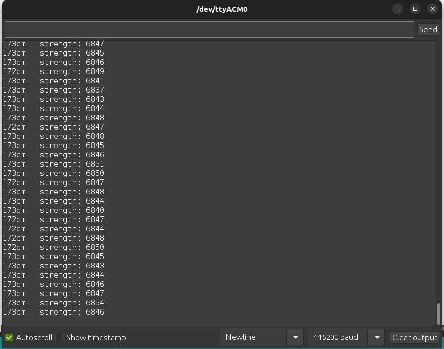
The above sketch ran successfully without any errors upon uploading it to the Arduino UNO R3 microcontroller board and this was the output.
Final Output
Output at the Serial Monitor
We tested the TFMini-S LiDAR sensor module by measuring different distances for-example we measured the distance between the working table and the ceiling indoors and this was the reading on the serial monitor
Working Demo
Downloads
You can find all the necessary files for this project in this Github Repository.
Conclusion:
In this project-tutorial, we’ve learned how to interface the TFMini-S LiDAR time-of-flight distance sensor and the Arduino Uno R3 Microcontroller with the help of a 4-channel logic converter. We saw that the process is fairly simple (the errors we encountered were rectified with ease) and that the sensor can be used to measure distances of up to 12 meters. LiDAR sensors have a wide range of applications, and they can be used to improve the functionality of many Arduino and Raspberry Pi projects. If you are interested in learning more about building D.I.Y projects with Arduino, we recommend checking out our other Arduino projects here… Thank you for reading…. Cheers…
If you liked this project-tutorial about Interfacing the TFMini-S LiDAR Sensor Module with the Arduino UNO R3,
then please subscribe to our YouTube Channel for more D.I.Y projects-tutorials.
Leave a comment down below incase you have any questions about this project-tutorial.
Follow us on our different social media platforms;-
LinkedIn, Facebook, Instagram, TikTok, & Pinterest.







In the checksum calculations, the value of 256 is used to account for the fact that the distance and strength values are stored in two bytes each.
The TFMini sensor transmits data in a serial stream, where each data frame consists of nine bytes. The distance value is represented by the third and fourth bytes (
rec[2]andrec[3]), while the strength value is represented by the fifth and sixth bytes (rec[4]andrec[5]).Since each byte can have a value between 0 and 255, combining two bytes allows for a larger range of values to be represented.
To reconstruct the complete distance and strength values from the received bytes, the code multiplies the second byte by 256 and adds it to the first byte. This operation effectively shifts the second byte 8 bits to the left (equivalent to multiplying it by 256) and then adds it to the first byte.