Lesson-07 Series & Parallel Circuits
In this tutorial, we are going to look at the two circuit configurations that is, Circuits connected in series and circuits connected in parallel. We’ll see how they differ from one another using simple circuits containing the most basic of components, resistors, capacitors, inductors and batteries and also explore what happens when all these components are combined together.
Have a look at the previous tutorials;
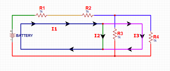
Consider the schematic below;
In the schematic above, there are four resistors (R1, R2, R3 & R4) connected to a battery, the electrical junction between two or more components is referred to as a Node. When we model an electrical circuit on a schematic, the Nodes then represent the wires between the components. Notice the Nodes (wires) in the above circuit have different colors.
So how does current flow in such a circuit?
What you should know first is that Current flows from a high voltage to a lower voltage (which is usually the ground) in a circuit and using the above circuit as an example, current will flow from the positive terminal of the battery to the negative terminal.
We also notice that the same current from the battery goes through R1 and R2 (in and out) and at the three-way junction between R2, R3 and R4, the main current splits into two and this is the main difference between series and parallel circuits.
So let’s differentiate the two;
-
Parallel Circuits;
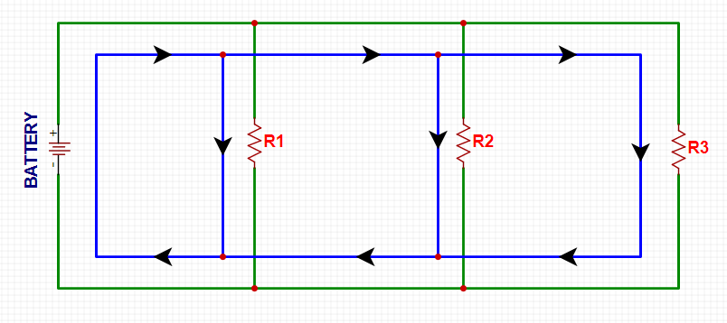
Consider the schematic of three resistors connected in parallel with a battery as shown below;
In the above schematic, we see that components share two common nodes and for this we say, they are in parallel. The node that connects the battery to R1 is also connected to the other resistors (R1 and R2) and the other ends of these resistors are similarly tied together and then tied back to the negative terminal of the battery. There are three different paths that current can take before returning to the battery and the associated resistors are said to be in parallel. From the positive terminal of the battery, current flows to R1, and R2 and R3.
N.B: So we notice that parallel components, all have the same voltage drop across them.
-
Series Circuits:
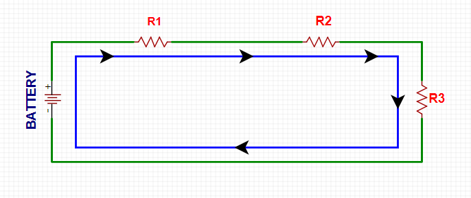
Consider the schematic of three resistors connected in series with a battery as shown below;
From the circuit above, we see that two or more components are in series if they share a common node and if the same current flows through them. For series circuits, there is only one way for the current to flow, that is, starting from the positive terminal of the battery, current will first go through R1, then R2, then through R3 and finally head back to the negative terminal of the battery.
N.B: So we notice that Series components, all have equal currents running through them.
-
Series and Parallel Circuits Combined:
So what happens if we mix and match the two circuit configurations?
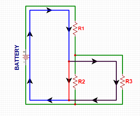
Let’s consider the schematic of three resistors connected to a battery as shown below;
In the schematic above, we can see that R2 and R3 are in parallel with each other and R1 is in series with the parallel combination of R2 and R3.
So how does current move in such a schematic?
From the positive terminal of the battery, current first goes through R1 but at the end of R1, the node splits into two and current can go to both R2 and R3. The current paths are then tied together again and current goes back to the negative terminal of the battery.
How to calculate equivalent Resistances in Series Circuits;
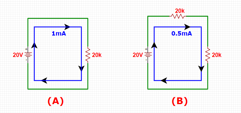
Let’s consider the two schematics A and B below;
One thing you should have noted by now is that, when we put resistors together like this in series or parallel, we change the way the current flows through them. For-example in schematic A above, we have a 20V power supply across a 20kΩ resistor and if we apply Ohm’s Law on this circuit, (i.e I=V/R), where I is current, V is voltage and R is resistance, we see that we’ve got 1mA of current flowing through that circuit.
If we then put another 20kΩ resistor in series with the first resistor and leave the power supply unchanged as shown in schematic B above. This means we are doubling the resistance and eventually cutting current in half. So by Ohm’s law we have 0.5mA of current flowing through the circuit B above.
What this means is that, current has only one path to take and we’ve just made it even harder for it to flow (that is we have 20kΩ + 20kΩ = 40kΩ).
So this is basically how we calculate resistors in series by just adding their values together and to put this equation more generally we see that the total Resistance “N” of resistors in series is their total sum as illustrated below;
R(total) = R1 + R2 + ….. +RN-1 + RN …………. Eqn 1
How to calculate equivalent Resistances in Parallel Circuits;
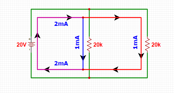
Let’s consider the schematics below;
When dealing with parallel resistors, it’s quite a different story. In the above schematic, we’ve taken the series Schematic A and added another 20kΩ in parallel instead of series with the same power supply. Now this means, there are two paths current can take and since the supply voltage didn’t change, upon applying Ohm’s Law, we see that the first resistor is still going to draw 1mA of current and so is the second resistor and we now have a total of 2mA of current coming out of the supply doubling the original 1mA. Now what this means is that we’ve cut the total resistance in half.
So how did this happen?
Well for any two resistors connected in parallel, we use a method called “product over Sum” to get the total resistance.
That is R(total) = (R1xR2)/(R1+R2) ………………… Eqn 2
= (400/40)
=10kΩ
And by Ohm’s Law, we have I = (20V/10kΩ) = 2mA.
Now one thing you should however is that we’re not always going to have two identical resistors in parallel. So what if we have more than two unequal resistors connected in parallel, what do we do? You ask!
Well for this, we use the reciprocal method and the equation for adding up an arbitrary number “N” of resistors connected in parallel is this;
1/R(total) = 1/R1 + 1/R2 + …… + 1/R(n-1) + 1/Rn ……………………. Eqn 3
Things you should note about Series and Parallel Resistors;
-
Equal Resistors in Parallel;
Adding up N-like-valued Resistors with Resistance R in parallel gives us R/N ohms. Let’s say we need a 5kΩ resistor and all we have is a bunch of 20kΩ’s, combining four of these 20kΩ’s in parallel gives us 20kΩ/4 = 5kΩ.
In other words, we can say that Total Resistance = Value of one resistor / Total number of resistors.
-
Different Resistors in Parallel;
The combined resistance of two resistors of different values is always less than the smallest value resistor. Let’s put this into practice so that you can comprehend it, let’s say we have two unequal resistors in parallel (that is a 10kΩ and a 20kΩ), by using the “product over sum” method, we see that we have our total resistance as 6.667kΩ which is less than the smallest value resistor which in our case is a10kΩ. Let that sink in.
-
Power Ratings in Series/Parallel;
Let’s say we need a 100Ω resistor rated for 2 watts (W) and all we’ve got is a bunch of 1kΩ half-watt (1/2W) resistors, you can then combine 10 of these 1kΩ’s in parallel to get 100Ω (1kΩ/10 = 100Ω) and the power rating will be 10×0.5W = 2W.
-
Power Dissipation in Parallel;
The power dissipated in a parallel combination of unequal resistor values is not split evenly between the resistors because the currents are not equal. For-example in a (1kΩ and a 10kΩ parallel configuration), we can see that the 1kΩ will be drawing 10x the current of the 10kΩ and since ohm’s law says Power = Voltage X Current, it follows that the 1kΩ resistor will dissipate 10x the power of the 10kΩ.
So basically tip #2 and #4 helps us to pay much closer attention to what we’re doing when dealing with unequal resistors connected in parallel. Tip #1 and #3 just offers some handy shortcuts when dealing with resistors of the same value.
-
Tolerance;
When it comes to tolerance, you need to know how much tolerance you can tolerate. Let’s say for-instance, you needed a 3.2kΩ resistor, you could put 3 10kΩ resistors in parallel and this would give you a 3.3kΩ total resistance which is a 4% tolerance from the value you need.
Series and Parallel Capacitors;
Combining capacitors in series or parallel connections is just like combining resistors but only the opposite. This sounds odd but it’s true and why is that? Let’s dig in and we explain a little further.
A capacitor is basically two plates spaced very close together and its basic function is to hold a bunch of electrons. So the greater the value of capacitance, the more electrons it can hold and if the size of the plates is increased, the capacitance also increases because there’s physically more space for electrons to hang out. If the plates are moved further apart, the capacitance decreases because the electric field strength between them reduces as the distance increases.
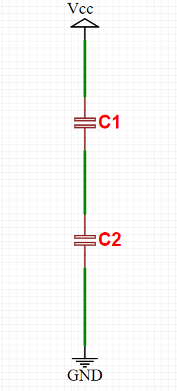
So let’s say we have two 20µF fully charged capacitors (C1 and C2) connected together in series and ready to discharge as shown in the schematic below;
(The space between the two capacitors’ plates is additive thus reducing capacitance).
Now, if we’re to recall, in a series circuit there is only one path for current to flow and it follows that the number of electrons that are discharging from the cap on the bottom is going to be the same number if electrons coming out of the cap on the top. So capacitance hasn’t changed, has it?
Explaining this a little further, by placing the capacitors in series, we’ve effectively spaced the plates farther apart because the spacing between the plates of the two capacitors adds together. So in the above circuit we have a total capacitance of 10µF.
So how did we arrive to that figure? Well we add series capacitor values the same way we add parallel resistor values that is, both the “Product-Over-Sum” and reciprocal methods are valid for adding capacitors in series as illustrated below.
C(total) = (C1C2)/(C1 + C2) ………….. Eqn 4
So the other thing you should note here with capacitors is series is that, we do get twice as much voltage (or voltage ratings). Just like in batteries, when we put capacitors together in series, the voltage adds up.
Capacitors in Parallel;
Adding capacitors in parallel is just like adding resistors in series, the value just adds up. So why is this? Let’s explain a little further, putting capacitors in parallel effectively increases the size of the plates without increasing the distance between them that is, more area equals more capacitance as illustrated in the figure below.
C(total) = C1 + C2 + ….. +CN-1 + CN …………. Eqn 5
It’s that simple.
How Series and Parallel Capacitors work in the real world;
Measuring capacitance directly with a multimeter is quite hard so this will be trickier than the resistors examples.
So before we dive in, let us first talk briefly about what happens when a capacitor charges up from zero volts. When current starts to go in one of the leads of a cap, an equal amount of current comes out the other and if there’s no resistance in series with the capacitor, it can be quite a lot of current. In any case the current flows until the capacitor starts to charge up to the value of the applied voltage, more slowly trickling off until the voltages are equal when the current flow stops entirely.
So we’ve seen that in the absence of a resistor in series with the capacitor, the current draw can be quite large and the time to charge can be very short (like milliseconds or less).
So before we go any further, we need to first of all talk about what an RC Time constant is;
Ʈ = R x C ……………… eqn 6
What this equation means is that, the onetime constant in seconds (called Tau, Ʈ) is equal to the Resistance in ohms times the Capacitance in farads. Let’s demonstrate this a little further.
So for this experiment, we want to be able to watch a capacitor charge up, so we’re going to use a 10kΩ resistor in series to slow the action down to a point where we can see it easily.
So using a 10kΩ resistor and a 100µF capacitor (which equates to 0.00001 farads), now these two create a time constant of 1second.
Ʈ = R x C = (10000Ω) x (0.0001F) = 1 second.
When charging our 100µF cap through a 10kΩ resistor, we can expect the voltage on the cap to rise to about 63% of the supply voltage in 1 time constant which is 1 sec. and after 5 time constants (5 sec in this case), the cap will be about 99% charged up to the supply voltage.
So now that we know enough theory, let’s put this into practice and we see how it works exactly.
You’ll need the following components for this experiment;
- Multimeter
- 10k Resistor
- 100F Capacitor
- Power supply (say 4.5V) with On/Off switch.
- Breadboard
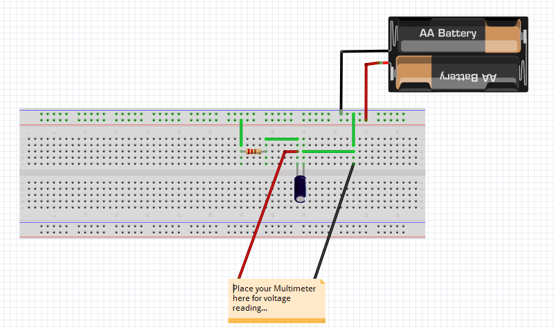
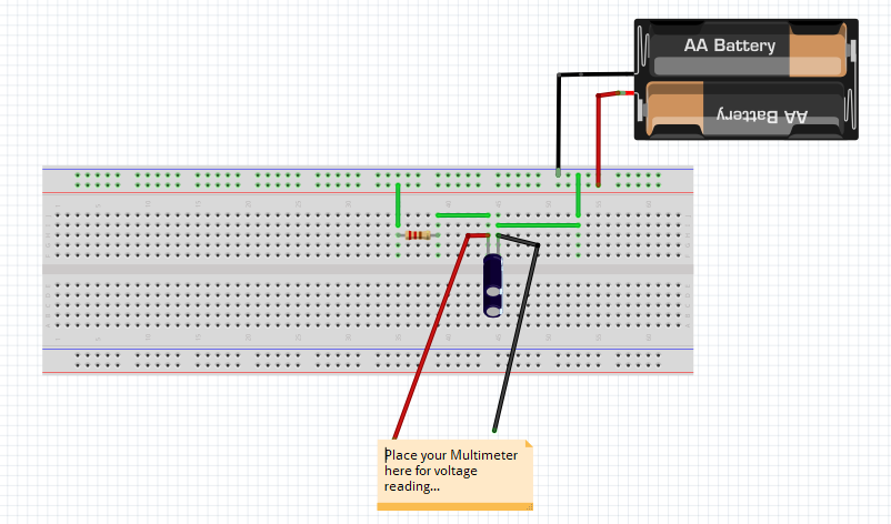
Construct your circuit as shown in the diagram below;
Now our multimeter is set to measure volts, check first to see the actual voltage reading of your power supply, and turn it OFF before plugging the leads into the breadboard ensuring the right polarity.
Once everything is nicely done, flip the switch on the battery pack to “ON” and after about 5 seconds, the multimeter should read the battery pack voltage (at least a figure very close). This demonstrates that the equation is right and we definitely know what we’re doing.
Now turn off the battery pack and watch what happens. The multimeter still reads the same voltage because the cap is still holding the voltage pretty well. This is because there’s no path for current to discharge to cap, we’ve got an open circuit and to discharge the cap, you can use another 10k resistor in parallel. In about 5 seconds, it will be back to zero.
So how does this work in a Series and Parallel Configuration?
Starting with a Series Capacitor Configuration;
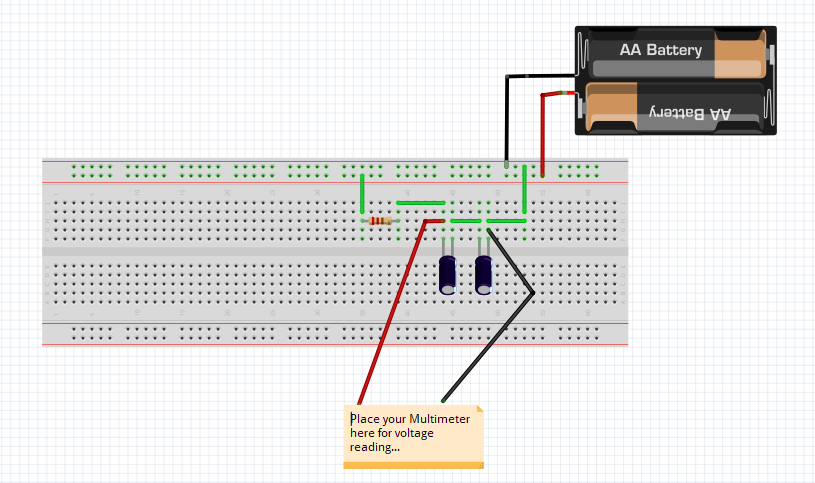
Let’s consider having two 100µF caps in series as shown in the Circuit below;
You should remember that capacitors is series operate in the same manner as resistors in parallel. So using the (Product over Sum) method we have a total capacitance of;
C = (100µF x 100µF)/(100µF +100µF) = 50µF
This means our Time Constant will become;
Ʈ = R x C = (10,000Ω) x (0.00005F) = 0.5 seconds.
Now upon flipping the switch on the battery pack, it will take about half as much time to charge up to the battery pack voltage. This is because there is much as half capacitance. That is the electron storage tank got smaller, so it takes less time to charge it up. You could experiment more with a third capacitor in series and see what happens.
Let’s look at a Parallel Capacitor Configuration;
Let’s consider having two 100µF caps in parallel as shown in the Circuit below;
You should remember that capacitors is Parallel operate in the same manner as resistors in Series. So we just add up the total capacitance.
C = (100µF +100µF) = 200µF
This means our Time Constant will become;
Ʈ = R x C = (10,000Ω) x (0.0002F) = 2 seconds.
So this means that it will now take about 10 seconds to see the parallel capacitors charge up to the supply voltage of 4.5V.
Now upon flipping the switch on the battery pack, it will take longer time to charge up to the battery pack voltage. This is because there is twice the capacitance. That is the electron storage tank got bigger, so it takes more time to charge it up. For more proof, you could experiment more with a third capacitor in parallel and see how much longer it takes to charge up.
Conclusion:
You now have the basic knowledge of how components such as resistors and capacitors operate in both series and parallel circuit configurations and how the current flows in both of these configurations plus how the voltage changes. You also know how capacitors behave (charge and discharge) in these two configurations. You could experiment more with components such as inductors that operate just like resistors do but for their case there is a catch, when placed close together they tend to have interacting magnetic fields so its preferable to have a single component instead of two or three plus most of them are shielded to prevent this effect. In the next chapter we’ll talk about How to use a Multimeter to measure current, voltage & resistance.


