Lesson-08 How to use a Multimeter
In this tutorial, you’ll learn how to use a digital multimeter (DMM). A Multimeter is an essential tool that is used to diagnose and troubleshoot circuits. It’s capable of measuring multi-ple things related to electricity such as voltage, current, resistance, continuity, capacitance and so on, hence the name “multimeter”. It is your number one go-to tool when troubleshooting any electrical/electronic system. So let’s see how we can use a Multimeter for measurement and testing.
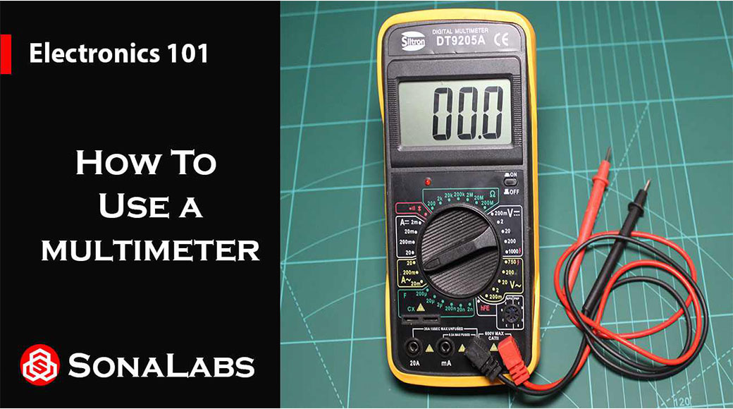
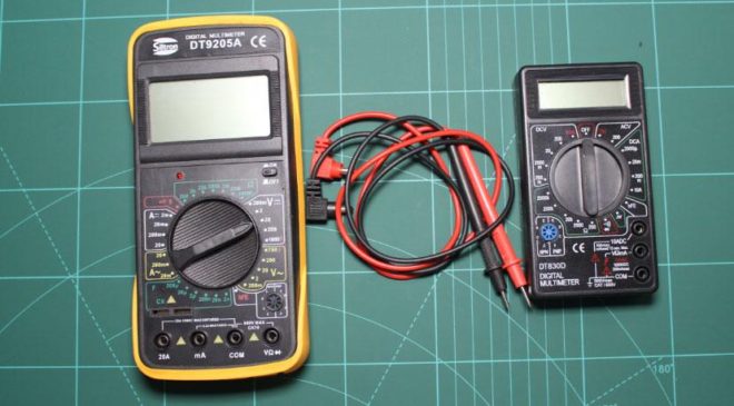
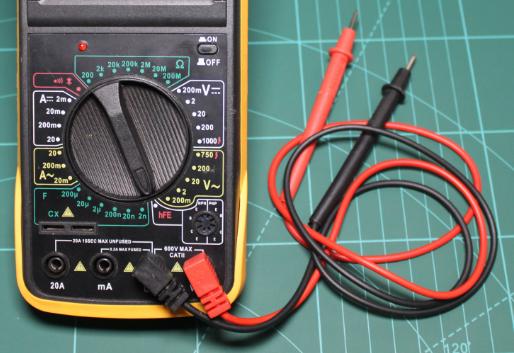
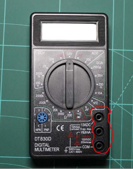
Please note; for this tutorial, we shall be using the “Siltron DT9205A and DT830D Digital Multimeters” as shown above. Worry not these multimeters have almost similar functionalities like that one you have or you intend to purchase. So let’s get started, shall we…
Have a look at the previous tutorials;
Lesson -07: Series and Parallel Circuits
The anatomy of a Multimeter;
A multimeter consists of three main parts and these are;
-
Display;
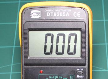
The display usually has four digits and it’s also capable of displaying a negative sign. Most multimeters have illuminated displays for better viewing in low light situations.
-
Selection Knob/Rotary Switch;
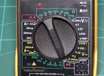
The selection knob allows the user to set the multimeter to read different things such as milliamps (mA) of current, voltage (v), resistance (Ω) and or capacitance (F).
-
Ports;
There are usually two probes that are plugged into two of the Ports on the front of the unit (these are conventionally red and black). These probes have a banana type connector on the end that plugs into the multimeter and any probe with a banana plug will work with this multimeter which allows for different types of probes to be used.
If we look at the DT830D Digital Multimeter, we see that we have three ports and these include;
COM – stands for Common and is almost always connected to Ground or “-” of a circuit. The COM probe is conventionally black but there is no difference between the red probe and black probe other than the color.
VΩmA – this is the port where the red probe is conventionally plugged into and this port allows the measurement of current (up to 200mA), Voltage (up to 1000VDC and 750VAC) and resistance (up to 200MΩ).
10ADC – this is a special port that is used when measuring large currents.
Looking at the DT9205A Digital Multimeter, we notice there are 4 ports, namely;
- VΩ ;- For measuring Voltage, Resistance and Diodes
- COM; – This is the common port that is always connected to ground.
- mA; – For measuring small currents.
- 20A; – Special port for measuring large currents.
Now that we know our way around a Multimeter, let’s see how we can actually use it for measurements;
-
Continuity;
Continuity is the act of testing the resistance between two points and it’s by far the single most important function for troubleshooting and debugging circuits. This feature allows us to test for conductivity of materials and to trace where electrical connections have been made or not made.
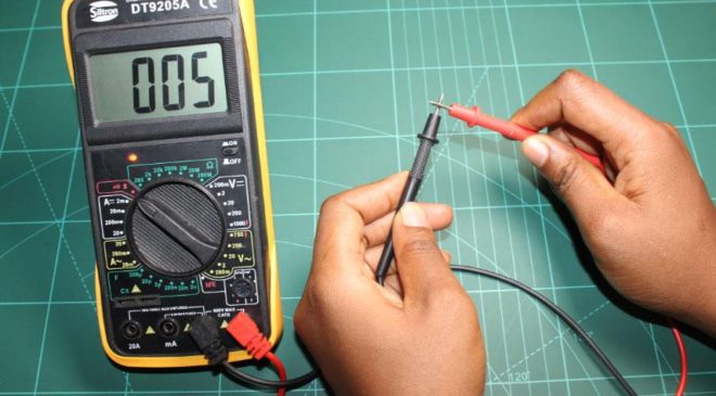
To use this feature, move the selection knob/rotary switch on the multimeter to the “Continuity Mode” this mode has a symbol of a diode with propagation waves around it (like sound coming from a speaker). Touch the two probe ends together and you must hear a sound.
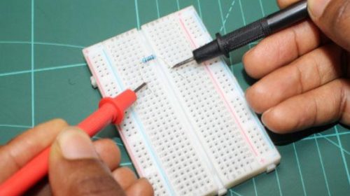
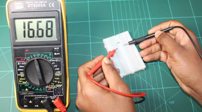
You can use this to test which holes on a breadboard are connected and which ones aren’t. You can also use this to trace out a circuit because you often can’t see where all of the wires go. If there is very low resistance (less than a few Ωs), the two points are connected electrically and a tone is emitted through the built-in buzzer. If there is more than a few Ωs of resistance, then the circuit is open and no tone is emitted.
This is a quick way to test to see if two points are connected correctly electrically and it also helps us detect if two points are connected that should not be.
-
Measuring Resistance;
Resistors (Through-Hole) are normally color-coded and for you to know the resistance of a given color-coded resistor, you’ll have to use some sort of a table or an online calculator to tell you the value. But in the event that you don’t have a table or an internet connection, then a Multimeter will come in handy at measuring resistance.
To use a multimeter for measuring resistance, set the selection knob/rotary switch to one of the resistance settings i.e (200, 2k, 20k, 200k, 2M, 20M, 200M). These are marked by the Omega symbol (Ω) and this represents the unit ohms which is used to measure resistance. Then pick out a random resistor to be measured and if you want to measure a small resistor to a high accuracy, then set the selection knob to the 200Ω setting, press the two probe ends on the resistor legs with some little pressure.
The multimeter will either give the actual resistor value as shown below or indicate 1 or 0.00.
If a multimeter displays [1. ], or “OL”, this simply means its overloaded, it senses the resistance to be greater than the range and you’ll need to move the range up a notch such as to 200kΩ or 200MΩ and measure the resistor again.
If it reads 0.00 or nearly zero, then this means you need to lower the mode to 2kΩ or 200Ω.
We should also note that since the display has no units on it, we assume that the number displayed matches the same units as the setting i.e if you have the range set to 200Ω, then the display will be in Ω and if you have the range in 2kΩ, 20kΩ 200kΩ then the value displayed will be in kΩ and the same applies for MΩ. For-example in the case above, the meter reads 0.87 meaning this resistor has a value of 870 since the knob is set in the kΩ range.
-
Measuring Voltage;
Voltage also referred to as Potential difference is basically the measurement of electrical potential between two points. On the multimeter, you’ll probably notice that there are two different ranges for measuring voltage i.e the one that has two straight lines which indicate Direct Current (DC) measurements that is most common with digital electronics and the one that has a wavy-like line which indicate Alternating Current (AC) measurements that is typically found in our electrical wall outlets. For our case, the 20VDC setting is probably the most typical for most of our applications.
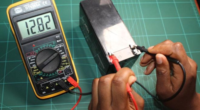
To use a multimeter to measure voltage of let’s say a 12V battery, plug the black probe into the COM port and the red probe in to the “mAVΩ” port or the VΩ port depending on the type of DMM you have and then move the selection knob/rotary switch to the desired VDC position. Then connect the black probe to the Ground or “-” terminal of the battery and the red probe to the power or “+” terminal of the battery and apply a little pressure and if you have a new battery, then you should see around 12V or higher on the display as shown below;
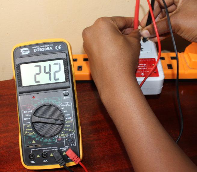
To measure AC voltage, connect the black probe into the COM port and the red probe in to the “mAVΩ” port or the VΩ port and move the selection knob/rotary switch to the desired VAC position. Connect the test leads across the source or load being measured and read the voltage off of the LCD display as shown in the figure below;
Please note: AC circuits can be very dangerous and they can kill you within a blink of an eye so we advise you to always use an AC tester while checking for AC.
-
Measuring Current;
For any given circuit, current is the rate of moving charges from positive (+) to negative (-) as we know it by convention. But we also know that it’s the movement of electrons. Now for us to be able to know the rate of moving charges, we have to break the circuit and put the multimeter in line with where we want to measure current.
So to do this, we have to move the knob to the appropriate current range that we expect to measure and if we’re to measure anything beyond 200mA or 0.2A, then we have to move the red probe to the 10A or 20A port.
Let’s say for-instance we want to measure the current going through a simple LED and resistor series circuit, we would have to first of all splice into the circuit just after the LED to ensure that the current path must go through the Multimeter. Please note that we cannot measure the current anywhere along the path since it’s a series circuit.
N.B:- You have to be careful when measuring current as you have to ensure not to exceed the limits because if you do so you’ll run the risk of blowing up the fuse of the multimeter. As earlier stated above, if you’re to measure currents above 200mA, you then have to move the red probe to the 10A or 20A port and also move the selection knob to the 10A or 20A setting respectively.
-
Measuring Capacitance:
To measure the capacitance of a given capacitor, move the selection knob/rotary switch to the desired F position. Then insert the capacitor to be measured into the capacitance testing socket and before doing this, ensure that the capacitor has been fully discharged.
In case you are to measure capacitors with shorter leads, use a testing adaptor that is usually provided with the meter. You should also note that when testing large capacitances, there will be a certain time lag before the final indication.
N.B:- To avoid electric shock, be sure the capacitor measuring adapter has been removed before changing to another function measurement.
-
Diode Test:
To perform a diode test of its forward voltage drop, connect the black probe into the COM port and the red probe in to the “mAVΩ” port or the VΩ port and move the selection knob/rotary switch to the desired position with a diode symbol.
Then connect the black probe to the Cathode or “-” terminal of the diode and the red probe to the anode or “+” terminal of the diode and apply a little pressure. The approximate forward voltage drop of the diode will be displayed and if the connection is reversed, only figure “1” will be shown.
-
Transistor Test:
To perform a transistor test, move the selection knob/rotary switch to the “hFE” position. Then determine whether the transistor under testing is NPN or PNP and locate the Emitter, Base and Collector leads.
Insert the leads into proper holes of the hFE socket on the front panel and read the approximate hFE value at the test condition of base current 10µA and Vce 3V.
Taking care of our Multimeter (Battery and Fuse Replacement);
If a battery symbol appears onto the display, it indicates the battery should be replaced. As for the fuse, it rarely needs replacement but it can blow as a result of operator’s error.
To replace the battery (9V) and fuse (200mA/250V), you’ll have to remove the three screws at the top and one screw at the bottom of the case as shown below;
Simply remove the old and replace with a new one and be careful to observe the battery polarity.
N.B: Before attempting to open the case, please ensure that the test leads/probes have been disconnected from the measurement circuits and after replacements are done, close the case and tighten the screws completely before using the multimeter again to avoid electrical shock hazard.
Conclusion:
By now, you probably know what a Multimeter is, why its called a multimeter and why a multimeter is such an important tool in the world of Electronics. You’ve learnt how it is used to measure multiple things such as voltage, current, resistance, continuity, capacitance and so on. In the next chapter, we will be looing at Buttons & Switch basics.


